Monday, February 22, 2010

Testing the sensors via serial communication.

Before using the Ethernet board I've done some test with the digital sensors and the 1-wire bus. In order to do that, I've attached the 1-wire bus in normal mode (3 cables, no parasite power) to the pin number seven of the Freeduino board and I've loaded the example program from the one-wire library's web page. Great success, fast and clean ;-)

Example program detects five sensors attached to the one-wire bus.

Monday, February 15, 2010

The ethernet board from Hong-Kong

Arduino uses an Ethernet board based on Wiznet W5100, however there are some alternatives a bit cheaper with their own libraries, in this case I’ve chosen an Ethernet adapter from seeed-studio (from China). The seeed-studio Ethernet adapter is based in a project from nuelectronics.com using an ENC28J60 Ethernet chip. The ENC28J60 will be responsible to manage the TCP connection, to do this, a number of packets needs to be exchanged between two sides first to establish the connection; then data packets can be exchanged. Usually a complicated state-machine is needed to implement the TCP protocol. For Auduino’s ATMEGA168, an 8-bit microcontroller with 1KB, it is impossible to implement the full TCP stack.  Therefore, instead of implementing full TCP protocol, a single data packet TCP protocol is used. The webpage contents, including all html tags, must be in one packet. The length of packet is limited to 500 bytes.
 Seee-studio ethernet adapter mounted on top of freeduino, 1-wire bus is connected to digital pin 7

Thursday, February 11, 2010

The sensors from Thailand

Happy day ! Today have arrived the sensors from a wholesaler in Thailand

Friday, February 5, 2010

The 1-wire bus

The 1-wire bus is a protocol from DALLAS semiconductor to implement a master-slave network of small devices. The network is controlled by a master (in this case the microcontroller) and n slaves which have an unique identifier of 64bits, the slave has the unique code buried within it. Only 3 cables are necessary to communicate with each node, ground, +5v and one data wire, although it is also possible to use the data cable as power source using an special work mode called "parasite mode".
  • The master starts a transmission with a "reset" pulse, which pulls the wire to 0 volts for 480 µs.
  • To send a "1", the bus master software sends a very brief (1 - 15 µs) low pulse.
  • To send a "0", the software sends a 60 µs low pulse.
  • When receiving data, the master sends a 1-15 µs 0 volt pulse to start each bit. If the slave wants to send a "1", it does nothing, if the slave wants to send a "0", it pulls the data line to ground for 60 µs.
The basic sequence is a reset pulse followed by an 8-bit command, and then data is sent or received in groups of 8-bits. There are several standard broadcast commands, and commands addressed to particular devices. The master can send a selection command, and then the address of a particular device, and then the next command is executed only by the selected device.

PCB implementing a 1-wire bus for testing purpouses

See 1-Wire devices
See One-wire library from Jim Studt, Tom Pollard & Paul Stoffregen

Wednesday, February 3, 2010

The arduino board (Freeduino CC)

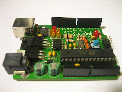
The main board of the project is the microcontroller, it is based on a Freeduino board which is fully compatible with the original Arduino the famous and well-known open-source electronics prototyping platform. The freeduino will be connected to the LAN through the Ethernet board shield mounted on top of it, and will communicate with the 1-wire bus through just one digital port (no more than one is needed). The microcontroller on the board is programmed using the Arduino programming language (based on Wiring) and the Arduino development environment (Arduino-0016). It can be programmed using a USB port which also supplies the power needed for the board. I've got it already mounted from a wholesaler from eBay Canada.

Freeduino board

Freeduino board


System architecture

The system architecture is easy; the micro controller will implement a micro http server accessible from a local area network through an Ethernet controller. If the local area network is accessible from internet even better, although in such case, some security issues may arise. The http request will trigger a temperature measure event; a specific message is published to the One wire bus and catch by all sensor which star individually to perform and A/D conversion during approximately 750 msec, after this period, the microcontroller address every sensor in order to retrieve the measured temperature, a web page is constructed with the information obtained and sent back as http response. The response time is about 1 second, not too match for a timeout. In order to get the http response independent from the A/D conversion time both (httprequest/response and temperature measure) should be implemented in separate threads, but a multithreading application may be difficult to implement in an 8bit microcontroller of just 8KB, I’ve seen some micro mini OS for AVR microcontrollers like FEMTOOS or PYXIS-OS which may solve the multithreading problem.

System architecture

Monday, January 5, 2009

The sensor

I've chosen a digital sensor in order to avoid A/D conversion and non-linear responses; the digital sensor performs the A/D conversion in-situ and implements the communication protocol to inform about the measurement. I've used the Maxim parametric search for temperature sensors for choosing the right one. I've decided to use the DS18S20 because:
  • Has a reasonable accuracy of 0,5ºC
  • The package is a TO-92 which fits fine at the places I want to install them without using a pcb
  • Implements 1-wire communication protocol
DS18S20 digital sensor